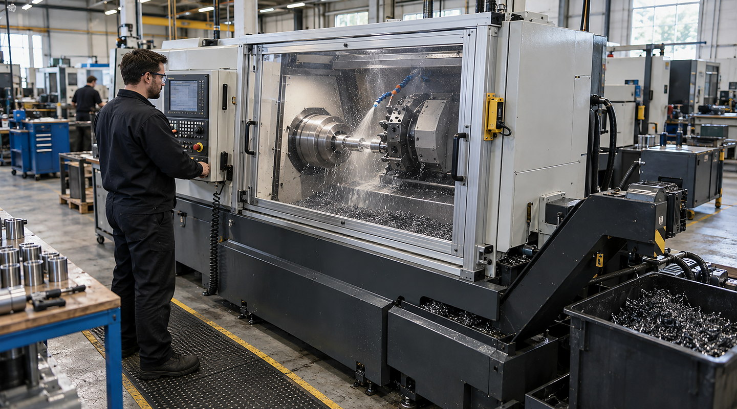
A drill-press guard must be assessed around the chuck, tool, spindle movement and workholding on the actual machine. The guarding brief should cover the smallest and largest jobs, normal adjustment and cleaning, so protection remains practical across the intended tasks.
Speak directly with Oxford Machine Guarding about drill-press spindle and chuck guards.
Quick answer
What should we consider when selecting a drill-press guard?
Record the drill press, tooling range, workpiece sizes and the movements needed for clamping and drilling. Include chuck access, tool changes and swarf removal in the assessment. Review the guard’s coverage, adjustment, mounting and any control interface against those tasks before accepting the installation.
Application decisions
Prepare the machine details that determine guard suitability
Decision 1
Map the full working envelope
Record quill travel, chuck and tool range, table movement and the largest intended workpiece. Include protruding clamps and fixtures. A guard that fits one demonstration setup may obstruct another job or leave access around a different tool position.
Decision 2
Review contact and ejection separately
Identify access to rotating parts and the possibility of ejected swarf, fragments or an unsecured workpiece. A visible shield is not by itself evidence that all of these hazards are controlled. The assessment must consider workholding and the rest of the machine.
Decision 3
Show how the work is clamped
Photograph the vice, fixture or other approved workholding in the intended positions. Explain loading and unloading tasks and access to the feed handle. Guard selection should be considered with the means of securing the work, rather than relying on the operator’s hand position.
Decision 4
Include tool changes and cleaning
List routine chuck access, drill changes, adjustments and swarf removal. Identify the isolation arrangements used for those interventions. The proposed guard should support the agreed safe working methods without encouraging operators to remove it for ordinary production.
Decision 5
Check mounting and visibility
Identify a suitable fixing location, movement clearance and the view of the drilling operation. Review vibration, adjustment retention and foreseeable damage. Mounting changes must be assessed for the machine; a nominal bracket dimension does not prove a safe installation.
Decision 6
Define installation checks
Agree inspection of coverage, adjustment, fixings and any interlocking function before return to service. Retain the task assessment and records of the modification. The guard integration guide helps organise the mechanical and control interfaces.
Applications
Existing drill or planned machine modification?
Review the workholding, tool range and access on the installed machine. A changed fixture, process or control arrangement may alter the guarding assessment even when the drill itself remains in place.
Collect machine details and photographs with representative workpieces, tools and workholding.
02
Assess the guarding concept
Have competent personnel review foreseeable access, ejection, stopping and intervention tasks.
03
Plan the machine modification
Agree mounting, adjustments, any control work and the installation responsibilities before fitting.
04
Inspect before use
Complete the required checks and update instructions, maintenance arrangements and records.
Important limits
Know what needs a separate check
Current standards and required performance levels must be assessed for the complete machine and intended use.
A site survey and task-based risk assessment are required before a safeguard is selected.
Mechanical changes can affect access, visibility, cleaning and machine operation.
Your final solution for drill-press spindle and chuck guards must reflect the law, current standards and site-specific risks that apply to your installation.
Compare a drill guard against the full working envelope
A drill-press guard must be considered alongside the spindle, chuck, tooling, workholding and the tasks used to set up the machine. A transparent screen and a guard that controls access can have different functions.